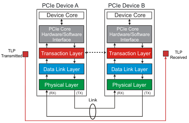
A TLP (Transaction Layer Packet) is the main “envelope” that carries PCIe transactions (reads, writes, config cycles, messages).
- Created in the Transaction Layer (Tx side)
- Decoded in the Transaction Layer (Rx side)
- Transported through Data Link + Physical Layers, which add/remove extra “wrapping” to ensure reliable delivery.
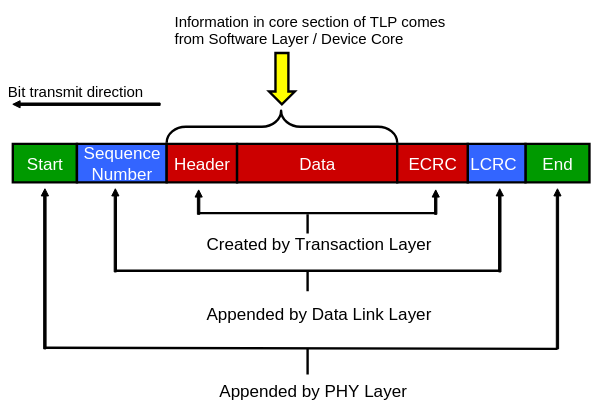
🏗 TLP Assembly (Transmit Path)
Think of TLP construction like wrapping a package in multiple layers of protection:
| Layer | What It Adds | Purpose |
|---|---|---|
| Transaction Layer (Red) | TLP Header (mandatory), Data (optional), ECRC (optional) | Identifies transaction type (read/write/etc.), target address, attributes. ECRC provides end-to-end error checking. |
| Data Link Layer (Blue) | Sequence Number, LCRC (Link CRC) | Ensures packets are received in the right order and without bit errors on this link. |
| Physical Layer (Green) | Start/End control symbols (Gen1/2) OR extra block framing bits (Gen3+) | Tells receiver where packet starts/ends, then serializes and transmits. |
| 📝 Key Detail: |
- ECRC = End-to-End CRC → Detects errors anywhere in the path, including switch internals (where LCRC gets recalculated).
- LCRC = Link CRC → Detects errors on the current physical link only. A new LCRC is computed at every hop.
📡 TLP Transmission Flow
- Transaction Layer: Core logic gives transaction info (address, type, data).
- Data Link Layer: Adds reliability metadata (Seq#, LCRC). Stores a copy to resend if NAKed.
- Physical Layer: Encodes, scrambles, and sends data over differential lanes.
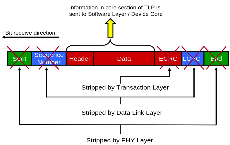
🛠 TLP Disassembly (Receive Path)
At the receiver side, the process reverses:
-
Physical Layer:
- Detects packet start/end markers
- Removes Physical Layer framing
- Forwards TLP + Data Link fields up
-
Data Link Layer:
- Verifies LCRC and sequence number
- If no errors → strips them out and forwards clean TLP up
- If errors → requests retransmission (NAK)
-
Transaction Layer:
- Optionally checks ECRC (if supported/enabled)
- Interprets header → passes data or command to Software Layer
- If device is a switch: uses header routing info → forwards packet to correct downstream port
🎯 Why Have Both ECRC & LCRC?
- LCRC ensures each hop is error-free, but is recalculated per link.
- ECRC is end-to-end — if a bit flips inside a switch fabric (not covered by LCRC), the target device can still catch it.
📦 Visual Summary